The mechanical seal locating pin on the main shaft of a petrochemical plant hydrocracking compressor has failed. The material is 45 steel, the diameter is 4 mm, the material is quenched and the surface is chrome-plated. The chemical composition inspection results of the same batch of materials meet the standard requirements, and the working temperature of the compressor is 50-130 °C. In order to find out the cause of the fracture failure of the mechanical seal locating pin, a series of experimental analysis of the locating pin was carried out to prevent the recurrence of similar accidents. 1 Physical and chemical testing and analysis 1.1 Macroscopic analysis The failure of the locating pin was placed under a magnifying glass for macroscopic observation. It was found that the surface of the fracture was rough and there was no obvious plastic deformation. There are concentric circular groove marks on the end face of the locating pin, and there is a penetrating crack in the center of the end face. The surface of the end face chamfer has pits of different sizes and shades. The shape of the crack on both sides of the locating pin busbar is not completely symmetrical, indicating that the surface has particles falling off during the crack formation process. The macroscopic test results show that the locating pin is subject to wear during work and the material is brittle fracture failure. 1.2 Micro-morphology analysis The locating pin was placed in an ultrasonic cleaning machine and the fracture was observed by scanning electron microscopy. It can be seen that there is a secondary crack in the fracture, and a smooth and bright region of the circular wear scar DDD with a circumference of 50% is clearly visible at the edge, and the maximum radial depth of the wear scar is about 0.1 mm. The fracture is characterized by a typical rock-grain block-like crystal fracture morphology, and the intergranular porosity is loose. The end of the fractured ring-shaped wear scar coincides with the bus-side crack. The morphology of the locating pin was observed under scanning electron microscopy. The cracks inside the crystal were observed. The maximum thickness of the corrosion product layer on the surface of the locating pin was more than 0.02 mm. The internal structure was loose and porous. There was microcrack between the interface and the local corrosion layer. The inside of the surface of the material; the outer surface of the locating pin is chrome-plated, and the inner surface of the chrome-plated surface is corroded by the S-containing medium, but is tightly bonded to the base material. At the same time, the corrosion of the end of the positioning pin is more serious than the outer surface of the circumference. The microscopic analysis shows that the locating pin is severely worn in the fracture area, and the locating pin is corroded by the S-containing medium during the working process, and the end corrosion is particularly serious. 1.3 Energy spectrum analysis The energy spectrum analysis of different parts of the fracture surface of the uncleaned locating pin shows that there are S elements on the surface of the locating pin fracture, and the content is high, the local area is as high as 20% or more. In addition, after the locating pin is cleaned The energy spectrum analysis of the fine particles in the fracture, the end face in the metallographic surface and the oxide layer on the outer surface showed that the oxide layer contained a large amount of S elements, both of which were above 10%. In addition to the S element in the oxide layer, a Cl element is present in a localized region. The energy spectrum analysis shows that there is S element in the working medium of the locating pin, the surface of the fracture contains the corrosion product of S, and the end surface and the outer surface are corroded by the S-containing medium. 1.4 Metallographic analysis and hardness test The locating pin has a fine grain structure and maintains the martensite orientation of the tempered sorbite, with a strip-shaped and feather-like martensite morphology interposed. The chamfers and the crystal grains near the edge of the end are coarse, and the microstructure is distributed in the form of white ferrite. Some of the ferrite expands in a needle shape and there is a secondary crack in the fracture. The hardness of the locating pin was measured with a Vickers hardness tester. The result showed that the hardness of the material was as high as 58 HRC, which met the hardness requirement of the material after quenching treatment. In the metallographic diagram, the grains at the near end and the chamfer are thicker than other parts, indicating that the strength, ductility and toughness of the material at the end and chamfer are worse than those of the core, and the coarse grains will reduce the stress resistance of the material. The ability to corrode. 2 Analysis of the failure of the positioning pin combined with the working environment conditions of the positioning pin and the above physical and chemical inspection results, comprehensive analysis of the failure reason of the mechanical seal positioning pin. First, the operating temperature of the locating pin is 50-130 ° C. It is known from the literature that the material is subjected to tensile stress and has the possibility of reversible hydrogen embrittlement at -100 to 100 ° C, and the hydrogen embrittlement sensitivity of the material increases with the increase of hydrogen content. The increase in the degree of cracking shortens the gestation period, so that the pinching action of the locating pin increases the possibility of hydrogen embrittlement. Secondly, the high-speed operation of the hydrogen compressor not only causes the locating pin to be subjected to the vibration load during operation, but also causes the sealing assembly to squeeze the locating pin. From the working position where the positioning pin is located, the sealing assembly limits the axial displacement of the mechanical sealing locating pin, and the locating pin and the main shaft are in a clearance fit. Therefore, the vibration of the locating pin caused by the hydrogen compressor and the resulting The squeezing action of the sealing assembly on the locating pin will result in fretting wear under conditions of limited axial displacement. The asymmetry of the macro-cracks of the locating pin sample and the ring-shaped wear scar characteristic of the fracture micro-morphology indicate that the locating pin is subjected to wear and its ultimate destruction. In addition, the 58HRC high-hardness locating pin is hydrogen-free so that the generation of the shoulder crack is independent of the quality of the bonding layer of the roll. In summary, the cause of roll cracking should be due to the first stage of tempering stress and the superposition of stress during the second stage of tempering heating. In order to thoroughly investigate the causes of cracks, the heat treatment process of the rolls was analyzed. It was found that there were some shortcomings in the original heat treatment process. In the original heat treatment process, in order to ensure the transformation of retained austenite to martensite, After a period of tempering, a long period of air cooling is used, which increases the amount of retained austenite to martensite, but at the same time produces a large phase transformation stress, especially in the case of low winter temperatures. Under the pressure, the cracks are statistically found. The heat treatment cracks of the rolls are more from November to March of the next year, which further confirms that the excessive phase transformation stress is the main cause of cracks. 2 Heat treatment process improvement measures It can be seen from the analysis of crack causes that the heat treatment cracking of centrifugal composite high chromium cast iron rolls is mainly related to the first stage of tempering cooling, air cooling and the second stage tempering during heat treatment. The key to process improvement is to improve the above three aspects. Firstly, the first stage of tempering and cooling is improved, and the cooling rate in the original process is reduced by 2~3°C/h, so that the cooling process tends to be gentle; secondly, the air cooling section of the original process is improved, and the original process hollow cooling time is At 24h, the supersaturated martensite remains for a long time at low temperature, which increases the probability of crack generation. After the process is improved, the air cooling time is shortened as much as possible, and the air cooling time is adjusted according to the change of room temperature. The lower the room temperature, the shorter the air cooling time, the roll The second stage of tempering is performed immediately after the temperature reaches the required temperature; finally, the temperature rise rate at the second stage of tempering is lowered, and the original temperature increase rate is lowered by 3 to 5 ° C / h. After the implementation of the new process, the heat treatment crack of the centrifugal composite high chromium cast iron roll did not reappear. 3 Conclusion During the heat treatment of the centrifugal composite high-chromium cast iron roll, the first stage tempering is too fast, the air cooling time between the two stages of tempering is too long, and the second stage tempering is too fast, which is the main cause of the heat treatment crack of the roll. The first stage of tempering cooling rate, controlling the air cooling time between the two sections of tempering, reducing the heating rate of the second stage of tempering, can eliminate the heat treatment crack of the centrifugal composite high chromium cast iron roll.
here are two basic types of self adhesive labels: permanent and removable. Each type of adhesive is made from a variety of glues depending on the conditions the label will have to endure, the length of time it is required and the environment or conditions of storage.
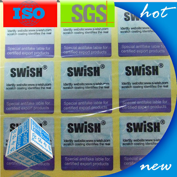
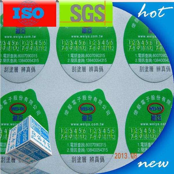
Self Adhesive Label use glossy paper, matt material to print CMKY color. It is print by oil, it can be also add series number, QR code, scratch off part in self adhesive label.
Kindly see below self adhesive label, which we can accpet OEM label.
Just need your logo in AI, CDR, EPS file, tks.
Self Adhesive Label Printing,Self Adhesive Labels,Self Adhesive Label 3D Printing Shenzhen Tuteng Anti-Counterfeiting Co., Ltd. , https://www.holographicsticers.com
Self Adhesive labels are usually coated with an acrylic, rubber or water-based glue. Sticky labels can either be applied permanently or temporally.
Self adhesive labels can printed on by laser printers, inkjet printers, photocopiers or handwritten. Laser printers and photocopiers are a hot process and we recommend that A4 sheets of labels are only printed once for best results. The heat process evaporates the moisture in the adhesive each time it is passed through the printer.


Research and solution to the problem of locating pin failure
The hydrogen compressor is one of the key equipments of the hydrocracking unit. The main function is to supply a certain pressure of hydrogen to the cracking furnace to ensure the continuous and stable operation of the heavy oil cracking reaction. Therefore, the performance of the hydrogen compressor directly affects the smooth production of the entire cracking unit.