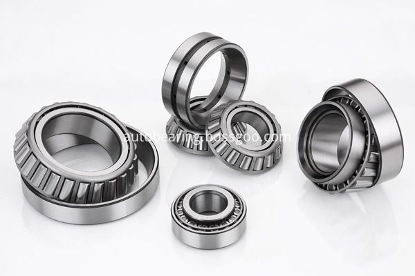
Tapered Roller bearings are
radial thrust rolling bearings with tapered roller. There are two kinds of cone
angle and big cone angle .Small cone angle mainly bear radial direction load
primarily radial and axial loads, often used in pairs, reverse installation,
inner and outer ring can be installed separately, in installation using radial
and axial clearance can be adjusted; Big cone angle mainly bear axial load
primarily of axial and radial load, is generally not used to bear alone the
pure axial load, as to the pair (end with the same relative installation) can
be used to carry pure radial load.
Tapered roller bearings are
widely used in automobile, rolling mill, mining, metallurgy, plastic machinery
and other industries.
Range of size are below:
Single row tapered roller
bearing:
Inner diameter range: 20mm ~
1270mm.
Outer diameter range: 40mm ~
1465mm.
Width: 15mm ~ 240mm.
Double row tapered roller
bearing:
Inner diameter range: 38mm ~
1560mm.
Outer diameter range: 70mm ~
1800mm.
Width: 50mm ~ 460mm.
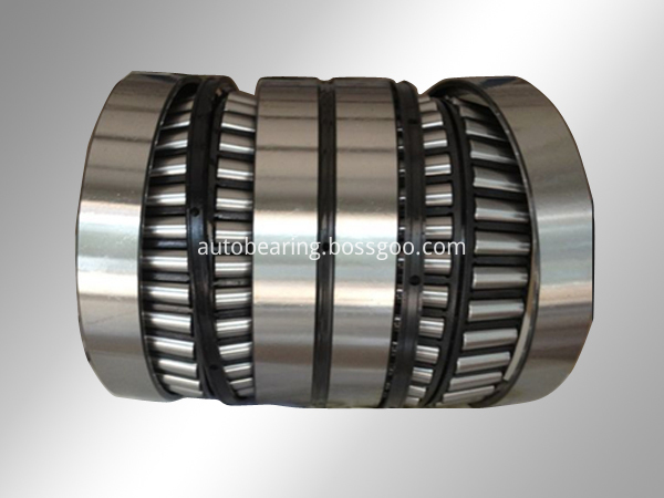
Four row tapered roller
bearings:
Inner diameter range: 130mm ~
1600mm.
Diameter range: 200mm ~
2000mm.
Width: 150mm ~ 1150mm.
The precision we can produce
P0~P2.
We believe that we can supply the best service and price for your,
hope to make a long-term cooperation with you. If you have any question please
do not hesitate contact with us. We keep warmly welcome you visit us in any
time.
Tapered Roller Bearing,Roller Bearing,Taper Bearing,Tapered Roller LUOYANG AUTO BEARING CO.,LTD , https://www.lyautobearing.com
Building a Well-off Society in an All-round Way: The Historical Responsibility of Chinese Science and Technology Workers A Constant Unit Power Factor Operation Strategy for Induction Motors Zhang Qingxin Wang Fengxiang Li Wenjun In recent years, new technologies for active compensation in power electronics research have been developed, and active power filters have achieved The harmonic pollution generated by the linear power device is suppressed; the unit power factor rectifier minimizes the harmonics generated by the AC-DC rectifier. Based on active compensation technology, this paper proposes a constant unit power factor operation strategy for induction motor, which uses active compensation technology developed in recent years in the field of power electronics to be used in induction motors to realize induction motors in any working condition. Constant unit power factor operation under conditions. The operation strategy mainly adopts a method of controlling the current on the grid side, that is, regardless of the load characteristics, the active filter forces the grid side current to be sinusoidal and in phase with the voltage. The traditional compensation method based on instantaneous reactive power theory is to control the output current of the inverter, so it is necessary to detect the load current. The method of controlling the current on the grid side does not need to detect the load current, which reduces the system to the current sensor. The need, such a running strategy, the magnitude of the current measured by the grid is determined by the power balance between the grid, the inverter and the motor, and the capacitor on the DC side is used to store the active power, without considering the system loss, there is no active Power flows through the inverter, so the average voltage across the capacitor is a constant value. When a power imbalance occurs, the difference in power between the grid and the motor is injected into the storage capacitor through the inverter. If the useful work power provided by the grid is less than the demand of the motor, the average voltage of the capacitor is reduced, the amplitude of the grid side current is increased, and the output power of the grid is increased; if the active power provided by the grid exceeds the demand of the motor, the average voltage of the capacitor is increased. The amplitude of the current on the grid side is reduced, so the average voltage of the capacitor provides information on the flow of active power, and the amplitude control of the current on the grid side can be achieved by adjusting the voltage of the capacitor. In this way, through the application of the active compensation technology in the induction motor, the induction motor can be operated under the constant unit power factor, and the amplitude of the grid side current is reduced, thereby achieving the purpose of energy saving.
The college is engaged in teaching and research work, lecturer, and pursuing a doctoral degree at Shenyang University of Technology. Mainly engaged in the research of electronic motors and their control systems, published more than a dozen papers in academic journals.
Power frequency test transformer computer control system Zhang Chao Li Wei At this stage, the theory of 篼 voltage insulation is not perfect. The existing theory of high-voltage electrical equipment insulation design sometimes can not meet the technical requirements, so the insulation of high-voltage electrical equipment in the product stereotypes, factory and Strict insulation test should be carried out during operation to ensure that the insulation of high-voltage electrical equipment can operate safely and reliably in the field.
This paper introduces a computer control system for power frequency test transformers that control, protect and measure, record and output power frequency test transformers with industrial computer as the center. The system has all the functions of the traditional power frequency voltage test. The digital test is used to complete the grading rise and fall test time. The test parameters and test procedures are available in several ways. The system also uses a computer to monitor the power frequency high voltage test in real time. Once the fault occurs, it will automatically alarm and timely protect it to avoid damage to the test equipment or sample, and ensure the safety of the personnel. The measurement uses computer-by-point sampling to find the peak in software, and gives theoretical error analysis and test results. When a discharge occurs during the test, the measurement program is designed to achieve a sufficiently fast tracking level to ensure accurate discharge voltage measurement. This program also has many functions such as judging over-limit, breakdown, timing, and digital filtering. The system anti-jamming has also been carefully designed, using shielding technology, anti-interference power supply, photoelectric isolation and other measures, so that the computer device can still operate normally under high voltage discharge. The system also retains the traditional manual console for the operation or emergency treatment of the power frequency high voltage test when the microcomputer fails or in some special occasions.
College of Electrical Engineering; Research on Design and Test Method of Electric Power Supply for 500kV Shunt Reactors Zeng Linsuo Liu Zhuo This paper raises the questions raised by the test power supply and test methods for the manufacture of 500kV shunt reactors in the actual production of Shenchang Company. The design and research, combined with the company's existing sites and equipment, carried out detailed analysis, a large number of comparisons and calculations, and obtained a technically feasible and economically optimal solution. Through the creative design work, the first large-scale high-voltage capacitor tower with multiple voltage switching and wiring methods was designed and built in China, which not only satisfies the requirements of temperature rise, magnetization characteristics and induction of current 500kV shunt reactors, but also It can meet the needs of the temperature rise test of the Three Gorges 500kV and 840MVA three-phase power transformers in the near future. At the same time, it can also meet the test requirements of the converter transformer in the *500kV DC transmission line.
The test of this new product is the first time for Shenchang Company. This paper theoretically analyzes the test method. And used in practice, and achieved satisfactory results.
In addition, this paper also introduces the further application of the capacitor tower to the test capability of the five-factory test bench.

